Watch this lesson
Video 10.1 ·
6:59 · What each gate does, and the truth table that defines it
1. The 6 Standard Logic Gates
Each gate has a specific logic rule and a corresponding truth table showing every possible input/output combination.
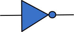
NOT Gate
Output is the inverse of the input.
A
OUT
0
1
1
0
AND Gate
Output is 1 only if BOTH inputs are 1.
A
B
OUT
0
0
0
0
1
0
1
0
0
1
1
1
OR Gate
Output is 1 if AT LEAST ONE input is 1.
A
B
OUT
0
0
0
0
1
1
1
0
1
1
1
1
NAND Gate (NOT AND)
Output is 0 only if BOTH inputs are 1.
A
B
OUT
0
0
1
0
1
1
1
0
1
1
1
0
NOR Gate (NOT OR)
Output is 1 only if BOTH inputs are 0.
A
B
OUT
0
0
1
0
1
0
1
0
0
1
1
0
XOR Gate (Exclusive OR)
Output is 1 if inputs are DIFFERENT.
A
B
OUT
0
0
0
0
1
1
1
0
1
1
1
0
2. Logic Algebra Symbols
In exams, you may see logic represented as equations:
AND: $A \cdot B$ or $A \text{ AND } B$
OR: $A + B$ or $A \text{ OR } B$
NOT: $\bar{A}$ or $\text{NOT } A$
⚠️ Exam Note: When drawing a logic circuit from an expression like $X = (\text{A AND B}) \text{ OR (NOT C)}$, always work from the inside of the brackets outwards.
Logic in Real-Life
Watch this lesson
Video 10.2 ·
8:09 · Turning a written scenario into an expression and a truth table
1. Sensors as Logic Inputs
In automated systems, sensors provide the binary input (0 or 1) based on a threshold value. For example:
Temperature: 1 = Too Hot 0 = Normal
Pressure: 1 = Pressed 0 = Not Pressed
Light: 1 = Dark 0 = Bright
Switch: 1 = Closed (On) 0 = Open (Off)
2. Worked Scenario: The Safety Alarm
The Problem: A chemical plant needs an alarm (X) to sound if:
The Temperature (T) is too high (T=1) AND the Pressure (P) is too high (P=1).
OR if the Emergency Switch (S) is pressed (S=1).
Step 1: Map the Logic
IF (T=1 AND P=1) OR (S=1) THEN X=1
Step 2: Create the Expression
X = (T AND P) OR S
Step 3: The Truth Table
This table shows when the alarm will actually sound based on the sensors:
T
P
S
X (Alarm)
0
0
0
0
0
0
1
1 (Switch pressed)
0
1
0
0
0
1
1
1 (Switch pressed)
1
0
0
0
1
0
1
1 (Switch pressed)
1
1
0
1 (Temp & Press high)
1
1
1
1 (All triggered)
3. Common Real-Life Examples
Street Lighting:Light Sensor (Dark) AND Timer (On) ➔ Lamp On.
Bank Vault:Key 1 (Turned) AND Key 2 (Turned) ➔ Door Opens.
Microwave:Timer (Not 0) AND Door (Closed) ➔ Start Cooking.
⚠️ Exam Note: Always read the "Conditions" carefully. Sometimes an exam will say "Alarm sounds if the window is NOT closed." If Closed = 1, you must use a NOT gate on that input.
Logic Expressions
Watch this lesson
Video 10.3 ·
9:23 · Moving between expression, truth table and circuit — in every direction the syllabus asks for
1. Understanding the Syntax
A logic problem can be represented three ways, and the syllabus expects you to move freely between all of them: as a logic expression, as a truth table, and as a logic circuit. This lesson works through every one of those conversions.
Expressions themselves can be written in two notations. You must be comfortable with both:
Textual: $X = (\text{A AND B}) \text{ OR (NOT C)}$
Symbolic: $X = (A \cdot B) + \bar{C}$
In symbolic notation, AND is a dot, OR is a plus, and NOT is a bar drawn over the top. The dot and plus are borrowed from arithmetic but do not mean multiply and add — they mean AND and OR.
2. Reading a Logic Circuit
A logic circuit is a diagram: inputs enter on the left, pass through gates, and produce an output on the right. Here is the circuit for the expression we will use throughout this lesson.
$X = (\text{A AND B}) \text{ OR (NOT C)}$
To write the expression from a circuit, work left to right, gate by gate:
1Label each gate's output. The AND gate takes A and B, so its output is A AND B. The NOT gate takes C, so its output is NOT C.
2Feed those labels forward. The OR gate's two inputs are the outputs you just labelled, so X = (A AND B) OR (NOT C).
3Bracket every gate output as you carry it forward. Without brackets, A AND B OR NOT C is ambiguous and will not be credited.
3. Worked Example: Building a Truth Table
Scenario: create a truth table for the expression:
X = (A AND B) OR (NOT C)
Step-by-Step Breakdown
1Identify Inputs: There are 3 inputs (A, B, C). This means there are $2^3 = 8$ possible combinations.
2Create Intermediate Columns: Solve the brackets first. Create a column for (A AND B) and another for (NOT C).
3Final Output: Use the OR gate to combine the two intermediate columns.
The Resulting Truth Table
List the input combinations by counting up in binary — 000, 001, 010, and so on — so that no combination is missed or repeated. The five highlighted rows are the ones where the output is 1; they are used again in section 4.
A
B
C
A AND B
NOT C
X
0
0
0
0
1
1
0
0
1
0
0
0
0
1
0
0
1
1
0
1
1
0
0
0
1
0
0
0
1
1
1
0
1
0
0
0
1
1
0
1
1
1
1
1
1
1
0
1
4. Writing an Expression from a Truth Table
This is the reverse direction, and it has a reliable method that always works. It is called the sum of products.
1Look only at the rows where the output is 1. Ignore every row where the output is 0.
2Write one AND term per row. For each of those rows, AND all the inputs together, putting NOT in front of any input that is 0 in that row.
3OR all the terms together. The output is 1 if any of those rows occurs.
Applying that to the five highlighted rows above:
Row A=0 B=0 C=0 → (NOT A AND NOT B AND NOT C)
Row A=0 B=1 C=0 → (NOT A AND B AND NOT C)
Row A=1 B=0 C=0 → (A AND NOT B AND NOT C)
Row A=1 B=1 C=0 → (A AND B AND NOT C)
Row A=1 B=1 C=1 → (A AND B AND C)
OR those five terms together and you have a valid expression for X.
Correct, but not tidy. That five-term expression and the much shorter
(A AND B) OR (NOT C) produce identical truth tables — they are the same
function written two ways. Sum of products is guaranteed to give you an answer, which
is what matters under exam pressure; it does not promise the shortest one. Unless a
question asks you to simplify, a correct sum-of-products expression earns the marks.
5. Drawing a Circuit from an Expression
To go the other way, work outwards from the brackets, exactly as you would evaluate arithmetic.
1Draw the inputs as labelled lines down the left-hand side, one per variable.
2Draw a gate for each bracket first.(A AND B) becomes an AND gate fed by A and B; (NOT C) becomes a NOT gate fed by C.
3Draw the gate that joins them. The OR in the middle of the expression becomes an OR gate fed by the two gate outputs.
4Label the final output X, and check that every input you listed is actually connected to something.
Here is a second circuit to read for practice. Work out its expression before checking the caption.
$S = (\text{NOT (P AND Q)}) \text{ OR R}$ — the bubble on the AND gate makes it NAND
6. Common Logic Gate Combinations
NAND Logic: $\text{NOT (A AND B)}$ is the same as saying "Output 0 only when A and B are 1".
NOR Logic: $\text{NOT (A OR B)}$ is the same as saying "Output 1 only when A and B are both 0".
On a circuit diagram, NAND and NOR are drawn as an AND or OR gate with a small bubble on the output. That bubble is the NOT. Missing it is the single most common mistake when reading a circuit, and it inverts every value in your output column.
⚠️ Exam Tips:
Always use intermediate columns. Even if the question does not ask for them, drawing them prevents logic errors that ruin the entire output column.
List input combinations by counting up in binary so none is missed or duplicated.
When reading a circuit, write the output of each gate onto the diagram before combining them.
Check for bubbles on gate outputs — they turn AND into NAND and OR into NOR.