Logic Gates and Circuits
1. The Half Adder
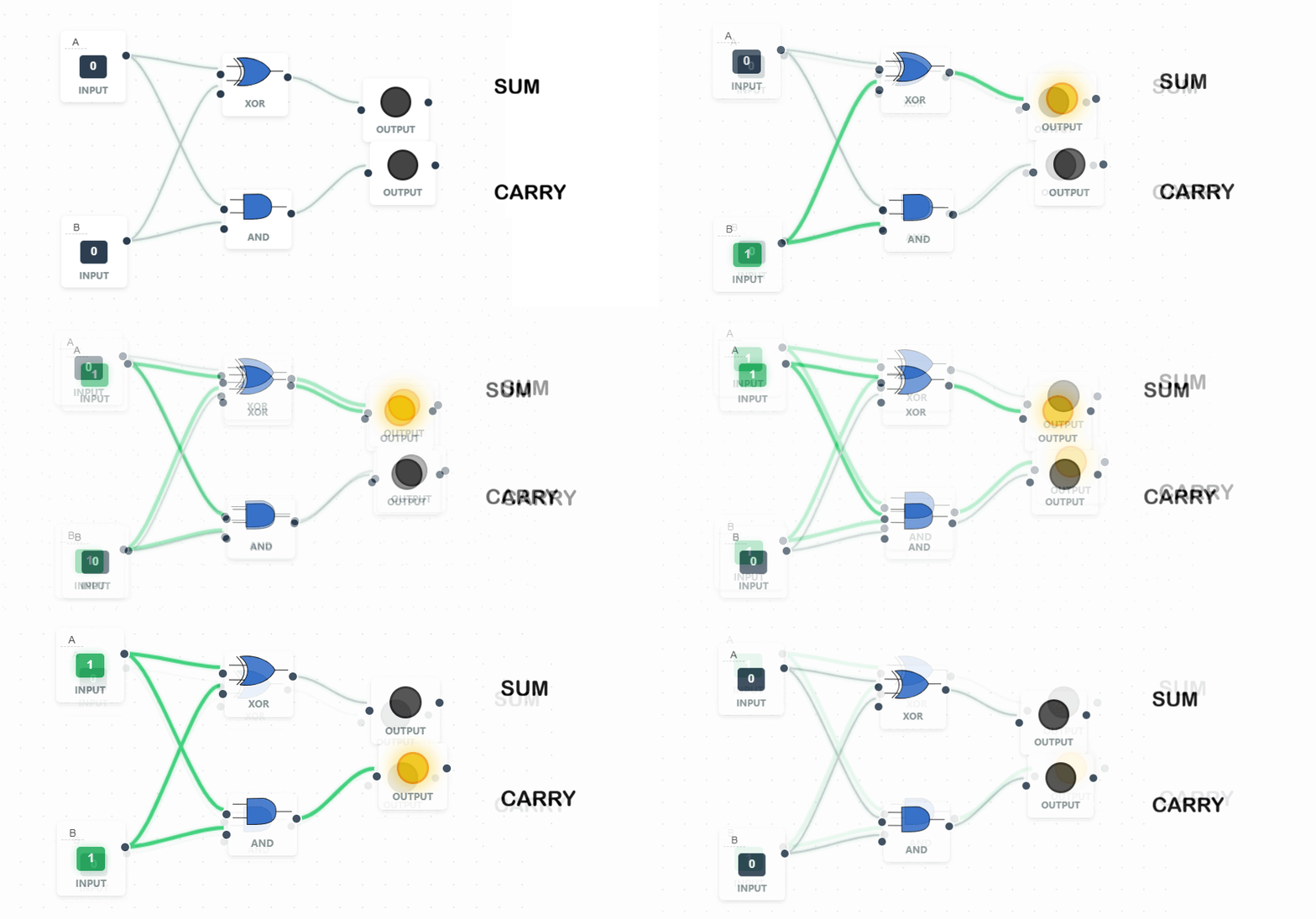
A **Half Adder** circuit adds two single binary bits (A and B). It produces two outputs: a Sum (S) and a Carry (C).
 ➔ Sum (S)
 ➔ Carry (C)
Sum (S) = A XOR B
Carry (C) = A AND B
Carry (C) = A AND B
| A | B | Sum (S) | Carry (C) |
|---|---|---|---|
| 0 | 0 | 0 | 0 |
| 0 | 1 | 1 | 0 |
| 1 | 0 | 1 | 0 |
| 1 | 1 | 0 | 1 |
Limitation: A Half Adder cannot handle a "Carry In" from a previous addition, which is why we need the Full Adder.
2. The Full Adder
A Full Adder adds three bits: A, B, and a Carry-in (Cin). This allows multiple adders to be chained together to add large binary numbers (e.g., 8-bit or 32-bit addition).
A Full Adder is constructed using two Half Adders and an OR gate.
Sum = (A XOR B) XOR Cin
Cout = ((A XOR B) AND Cin) OR (A AND B)
Cout = ((A XOR B) AND Cin) OR (A AND B)
| A | B | Cin | Sum | Cout |
|---|---|---|---|---|
| 0 | 0 | 0 | 0 | 0 |
| 0 | 1 | 1 | 0 | 1 |
| 1 | 1 | 0 | 0 | 1 |
| 1 | 1 | 1 | 1 | 1 |
3. Flip-Flops (Data Storage)
While adders do math, Flip-Flops are used to store a single bit of data. They are the fundamental component of Static RAM (SRAM) and CPU Registers.
- SR Flip-Flop: Uses NAND or NOR gates to "latch" a state. It has a Set and Reset input.
- JK Flip-Flop: An improved version that handles the "invalid" state of an SR flip-flop by toggling the output.
⚠️ AS-Level Exam Tip: You may be asked to show how many Half Adders make a Full Adder. The answer is always two, plus an OR gate to combine the carry bits.